
Indicator and Draw Diagrams
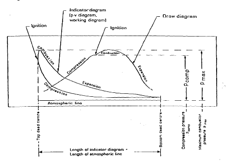 The draw diagram is used for measuring the compression pressure and maximum pressure, and for evaluating the ignition characteristics of the fuel oil.
The indicator diagram (pv diagram: work diagram), illustrates the pressure variations in the engine cylinder as a function of the main piston position. The diagram area can, be integrated by means of a planimeter, and the mean indicated pressure calculated. (Used with engines fitted with indicator drive or MIP-equipmen)
Fault finding from Draw card/ Indicator diagram
Diagram 1

Fuel injection too late.
Fuel pressure too low.
Detective fuel valve(s).
Defective fuel pump suction valve.
Exceptionally poor Fuel (bad ignition properties)
Fuel pump lead too little.
Diagram 2
Diagram 2

Fuel Injection too early (Fuel pump lead too large)
Diagram 3
Diagram 3

In diagram 3, Both Maximum pressure and compression pressure are low
Leakages, increased cyl. volume, or fouling.
Piston ring blew-by:
Exhaust valve seat leakage.
Piston crown burnt.
Low scavenge pressure.
fouling of exhaust and/or air system.
If you like our article, share it with your friends and VISIT OUR FACEBOOK PAGE AND LIKE IT(click here) to get all updates from us.
If you like our article, share it with your friends and VISIT OUR FACEBOOK PAGE AND LIKE IT(click here) to get all updates from us.
No comments:
Post a Comment